23K-star text-to-cad lets AI write CAD code for 3D prints
Follow one loop with text-to-cad: build a thin plate as STEP, export STL, measure its FDM wall thickness and fix it. Covers setup, stats opt-out, exit codes.
$ python scripts/dfam_tool.py measure STEP/bracket.step
{"error": "failed to load mesh: ..."}
$ echo $?
1
This is what happens when you feed a STEP file straight into the output-check skill of text-to-cad. It is not a malfunction, it is the design. The checker reads only triangle meshes, while STEP is a CAD model whose definition consists of faces and dimensions, so it has to be converted to STL first. Follow one loop, where the agent builds a model, exports STL, measures wall thickness, and if the wall is too thin, fixes the number and measures again, and you can see where and how this bundle of skills fits together.
On GitHub, earthtojake/text-to-cad has 23,284 stars and 2,260 forks as of Oct 27, 2026 (UTC), and it is MIT-licensed. That is up 125 from the 23,159 stars we saw a day earlier. The latest release is v0.7.26 from Oct 20, and there has been no new release since then through Oct 27, when this article was written. The job we follow here is an example made by our editors. We want to print a thin plate, 40mm wide, 20mm tall and 0.6mm thick, on a filament-based (FDM) printer. We chose 0.6mm on purpose so that the check would flag it, and the output figures below are diagrams built from the fields and exit codes in the documentation, not screens from an actual run.
Check for uv, and let the agent do the install
The first method the README recommends is to send the agent one sentence.
Install text-to-cad from https://github.com/earthtojake/text-to-cadIf you do it yourself, there are three steps. CAD runs go through uv, so check with uv --version whether it is installed, and if not, install it first with the uv installer. Then run the command listed for the app you use and restart the app. The first launch downloads the CAD runtime, so you need a network connection. For Claude Code it is two lines.
claude plugin marketplace add earthtojake/text-to-cad#latest
claude plugin install text-to-cad@earthtojake
The install and update commands for the other apps are below. Restart the app after every update.
| App | Install | Update |
|---|---|---|
| Claude Desktop | Add an MCP server (cadgen mcp) under Settings > Developer > Edit Config |
Change the number in cadgen==0.7.26, pinned in the config args, to the new release |
| Codex | The plugin directory, or codex plugin marketplace add earthtojake/text-to-cad --ref latest followed by codex plugin add text-to-cad@earthtojake |
codex plugin marketplace upgrade earthtojake |
| Cursor | git clone --depth 1 --branch latest … into ~/.cursor/plugins/local/text-to-cad |
git pull in that folder |
| Grok Build | grok plugin install earthtojake/text-to-cad@latest --trust followed by grok plugin enable text-to-cad |
grok plugin update text-to-cad |
| Gemini | gemini extensions install https://github.com/earthtojake/text-to-cad --ref latest --consent --auto-update |
gemini extensions update text-to-cad |
| Agents without plugins | npx skills add earthtojake/text-to-cad#latest (skills only) |
Run the same add command again |
The places where installs get stuck are well known. If you install both the plugin and the skills in one app, you end up with two copies of each skill, so pick one. The latest at the end of the command is a branch that receives only releases published to PyPI, and if you leave it out you get main, which may contain changes that have not been released yet. npx skills update misses newly added skills, so updating by running add again is the right way. The deprecated cad-viewer and cad-mcp-setup can be removed with npx skills remove cad-viewer cad-mcp-setup, and because the Codex marketplace name changed from text-to-cad to earthtojake, if you added it earlier, remove the old entry first.
On Windows 11 there is one more catch. The wheel for OCP (the Python binding for OpenCascade), the CAD kernel, contains an unsigned native module, so with Smart App Control turned on, every cadgen command ends with ImportError: DLL load failed while importing OCP. It is logged in Event Viewer as event ID 3077, and cadgen doctor points to the cause. There is no per-app exception, so you have to turn the feature off or run from WSL, and once Smart App Control is turned off, you have to reinstall Windows to turn it back on.
The usage stats the first command switches on, and the version check
This project sends usage statistics by default. The first cadgen command shows a notice once, and sending starts from that point. What goes out attached to a random install ID is the version, install source, OS and agent app, the number of calls per tool, the reason a call failed (one of a fixed set of words), the count, result and duration of builds and snapshots, and the features used. If cadgen’s own code fails, a crash report containing only the kind of error and the place it failed is also sent. The README states that file names, paths, contents and prompts are not sent. The server estimates the country from the connecting address but does not store the address, and the data accumulates in PostHog. By default nothing is sent from CI or development installs, and offline nothing goes out while every feature still works.
There are four ways to turn it off. uvx cadgen telemetry off turns it off and also deletes the data already sent. You can also turn off “Share usage stats” in the app menu (the logo at the top left), or ask the agent to turn it off. To turn it off for a single process only, use DO_NOT_TRACK=1 or CADGEN_TELEMETRY=0. Because sending begins with the first command, our editors recommend running this one line right after installing, before you give the first job.
Separately, a new-version check request goes out once a day to api.texttocad.dev/v1/versions. It is an anonymous request with no ID and no path, it is not sent from CI, and you turn it off with CADGEN_UPDATE_CHECK=0. Copies installed through the plugin directory, the Cursor marketplace or a Gemini extension are updated by the store, so this check is not needed for them.
Folder layout and one script
A model is a plain Python script in which an argument-free decorated function returns a build123d shape. The rules are short. The unit is millimeters, the default coordinates are the XY plane and the +Z direction, and meaningful dimensions are exposed as named constants. The shape must not change depending on time, random numbers, environment variables or the working directory. Keep one model per file, and the script and its output files share the same name stem. So src/bracket.py produces STEP/bracket.step and STL/bracket.stl, and the subfolder structure maps over the same way. The out= path in the decorator is relative to the script, not to the working directory.
Here is the plate example. WALL is the number we will keep fixing throughout this article.
from cadgen import build123d as bd
from cadgen import step, stl

WIDTH = 40.0
HEIGHT = 20.0
WALL = 0.6


@step(out="../STEP/bracket.step")
@stl(out="../STL/bracket.stl")
def bracket():
    body = bd.Box(WIDTH, HEIGHT, WALL)
    body.label = "bracket"
    return body


if __name__ == "__main__":
    bracket()
Running python src/bracket.py from the project root produces the STEP and the STL together. In the skill documentation, python is shorthand for uvx --no-config --managed-python --python 3.13 --from cadgen==0.7.26 python, so the agent runs it in that form. With the same input, running it again does nothing, and outputs that were deleted or overwritten by hand are restored. If it seems to rebuild even though nothing changed, cadgen store why src/bracket.py explains the reason, and to force the body of this model to run, use python src/bracket.py --force. After one loop, the folder looks like the figure below.
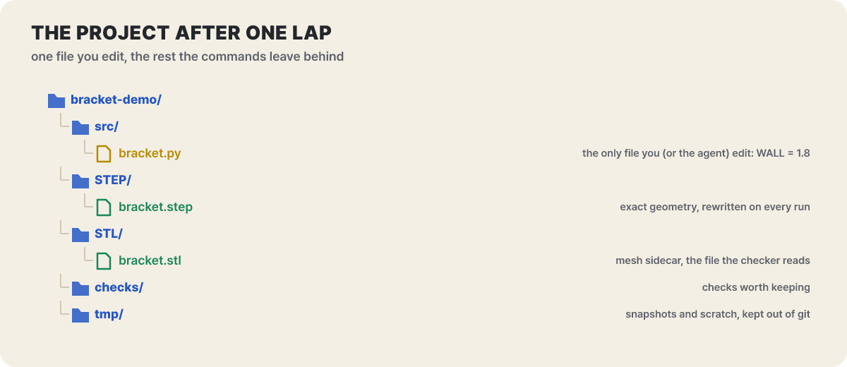 Figure 1. The only file a person edits is bracket.py. The rest is what the commands leave behind (a layout our editors drew following this article’s workflow)
Pulling one STL from one STEP
3D models fall into two kinds. STL and 3MF are meshes, with the surface cut into small triangles, while STEP is a boundary representation (B-rep) model that carries the definition of the shape itself, such as “this face is a cylinder 5mm in diameter”. A printer takes a mesh, but changing dimensions, assembling parts or producing drawings requires a B-rep. This skill set treats STEP as the source and produces STL, 3MF and GLB as derived files.
If you stack @stl on the function as in the script above, the STL is kept up to date on every run. To export just once from an existing STEP, use commands.
cadgen stl build STEP/bracket.step
cadgen 3mf build STEP/bracket.step
cadgen glb build STEP/bracket.step
If you omit the output path, the file is created next to the input with only the extension changed. These commands only read the saved STEP document and do not run the script again, so if you changed the model code, python src/bracket.py comes first. To keep resolutions separate, declare separate folders such as STL/draft/bracket.stl and STL/print/bracket.stl.
Two numbers decide how fine the mesh comes out. The default of --mesh-tolerance is 1.5e-3, a value relative to the length of the part’s bounding diagonal. The default of --mesh-angular-tolerance is 0.35 radians, the upper limit on the angle at which the normals spread at a triangle edge. The same input always produces the same bytes, so no chance creeps in when you compare while changing the values. The plate in this article has a bounding diagonal of about 44.7mm, so the chord error the defaults allow is about 0.07mm (our editors’ calculation). If you want a 0.1mm error on a 200mm part, pass 5e-4, which is 0.1 divided by 200. Values above 0.05 are rejected.
Never judge dimensions by looking at the mesh alone. A mesh has no CAD topology information, so accurate measurement is possible only from the STEP. Check the shape with a STEP snapshot.
cadgen step snapshot STEP/bracket.step tmp/review.pngIf you installed the plugin, a CAD viewer comes with it. In Claude Desktop and the Codex app it appears as a card you can rotate inside the conversation, and in Gemini, Grok and the terminal it gives you a link that opens in a browser. A face you pick in the viewer is attached to the prompt as a reference string such as STEP/assembly.step#o1.2.f7. That is why you can say “make the hole on this face 4mm” without opening the code. The numbers are valid only for one saved revision, so after a rebuild you have to pick again. Also, STL and 3MF cannot carry animation, only GLB can.
Feed STEP to the checker and 1 comes back
The dfam_tool.py tool of the DfAM Check skill has two commands. measure outputs facts such as wall thickness, overhangs and support volume as JSON, and orientations compares six axis-aligned orientations. For --angle-limit, give the angle at which the target process stands on its own (45 degrees for FDM). When the process changes, the support area is tallied by this angle, so you have to measure again. The tool only produces facts and does not say pass or fail. The skill’s procedure makes the judgment and reports only three outcomes: pass, fail and insufficient information.
The exit code is how this tool speaks. 0 means the report was computed in full, and 1 means the mesh could not be read at all. The STEP input at the start of this article falls here, and the skill documentation treats it not as a sign that a dependency package is missing but as a sign of invalid input. So it says to go the route of exporting an STL rather than installing more mesh loaders to work around it. 2 is a partial result in which only part was computed. If required dependencies were not fully installed and wall thickness could not be measured, partial: true is attached and the missing items are listed in partial_sections, and those items are treated not as 0 but as “insufficient information”.
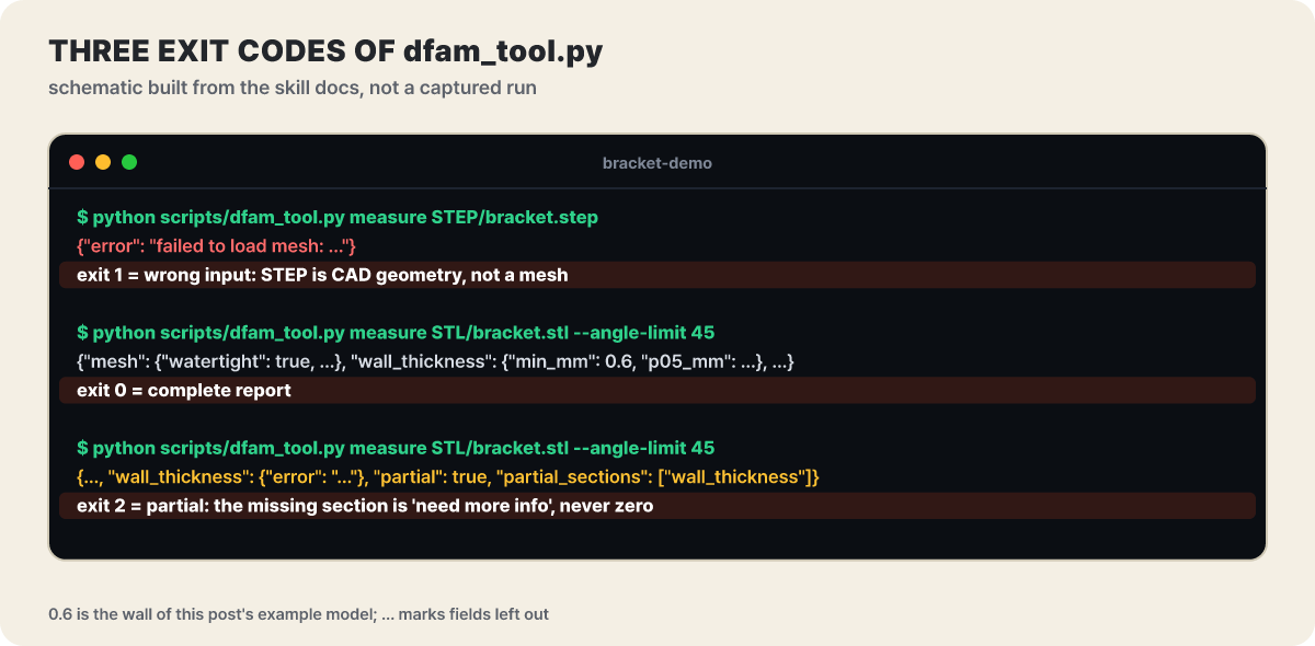 Figure 2. A diagram built from the fields and exit codes in the skill documentation, not actual execution output. 0.6 is the wall thickness of this article’s example model
What to look at first in the report is also fixed. If mesh.watertight is false, slicing is blocked for every process, so it goes ahead of any other finding. Check the units too. If scale.units_suspect, computed from the bounding box diagonal, is true, the source may be in meters or inches, and in that case overhang and support values of 0.0 mean nothing. The tool does not quietly scale the shape up or down. It asks you to confirm the units first.
The loop where a 0.6mm wall fails and 1.8mm passes
Now let’s measure the STL properly. At this stage you need to tell the agent the process, the material and the layer height. If it does not know the process, it measures once at the default 45 degrees and reports separately for each candidate process. The figure below shows the whole shape of the loop.
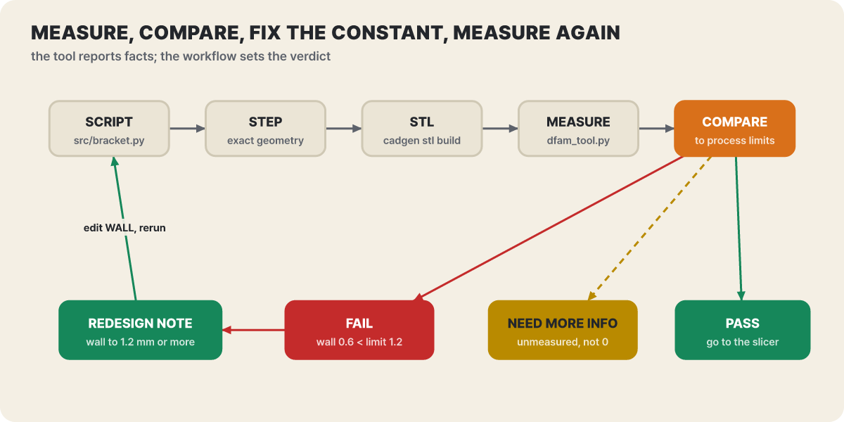 Figure 3. When a failure comes up, you fix the number and go around the same loop again. Items with insufficient information are not counted as 0 and remain on a dotted path
The rules of the comparison step are strict. Every finding has to state which row of the limits table and which measurement (the JSON field path) it was matched against. Wall thickness is measured by casting rays and sampling, so min_mm is not an exhaustive minimum. That is why, if p05_mm, the bottom 5% value, is smaller than the limit, it is reported as a violation even when min_mm looks like an outlier, and both values are written. Assemblies are measured per body (per_body) so that a gap where parts mate is not mistaken for a wall. A failed item gets a redesign instruction with numbers, such as “raise the wall from 0.6mm to at least 1.2mm”. The example in the documentation is exactly this sentence about raising 0.6 to at least 1.2.
- Describe the part and its use, then make the request. "Make a plate in src/bracket.py with the constants WIDTH 40, HEIGHT 20, WALL 0.6, and export the STEP and the STL."
- Ask "check the shape with a STEP snapshot" and look at the shape and dimensions yourself.
- Ask "check the STL for FDM, with a 0.4mm nozzle and 0.2mm layer height." The measured values should come back together with the row of the limits table they were compared against.
- The 0.6mm wall is thinner than the 1.2mm limit for supported walls, so it comes back as a failure. Have the agent apply the redesign instruction to the
WALLconstant, but where the wall is unsupported the limit is 1.6, so in our editors' example we raise it to 1.8, which clears both. - Rebuild the STEP and STL with
python src/bracket.pyand run the same check again. When the failed item disappears, stop here and check the result with your own eyes.
For the number in the fourth step, leaving some margin tends to get caught less on re-measurement than matching the limit exactly (our editors’ recommendation). When a CAD skill is present, the skill recommends the loop of fixing and measuring again, and has you repeat it until no failed items remain. This skill does not slice, upload or start a print.
Why the same wall passes on SLA
The verdict depends not on the file but on where you print. The limits table is in the repository’s process-limits.md, and it consists of conservative defaults fitted to the categories of ISO/ASTM 52910, with reference to the design guides of Hubs, Formlabs, HP and EOS. If the user provides the datasheet of the machine or material, that takes priority.
| Item (mm) | FDM | SLS (PA12) | SLA/DLP | Metal powder bed | MJF |
|---|---|---|---|---|---|
| Supported wall | 1.2 | 0.7 | 0.5 | 0.4 | 0.5 |
| Unsupported wall | 1.6 | 0.7 | 1.0 | 0.5 | 0.5 |
| Self-supporting angle (from horizontal) | 45 degrees | N/A (powder supports) | 30 degrees | 45 degrees | N/A (powder supports) |
| Minimum hole diameter | 2.0 | 1.5 | 0.5 | 1.5 | 1.0 |
| Minimum protruding feature | 0.8 | 0.8 | 0.2 | 0.4 | 0.5 |
| Maximum unsupported bridge | 10 | N/A | 5 | 2 | N/A |
Take a phone stand whose wall measures 1.0mm and hold it up against this table. On FDM, it is 0.2mm thinner than the 1.2mm limit for supported walls, so it fails, and the instruction is to raise the wall to at least 1.2mm. On SLA, the limit is 0.5mm, so it passes. However, the limit for unsupported walls on the same SLA is 1.0mm, so it sits exactly on the borderline, and because the self-supporting angle is 30 degrees, the overhang verdict also comes out differently from FDM. That is why the skill includes a procedure that says, if the process has not been decided, measure once and report separately for each candidate.
What the table lists but the tool does not measure
The tool does not measure all six rows of the table. What is measured today is only three items: supported walls, unsupported walls and the self-supporting angle. Minimum hole diameter, minimum protruding feature and maximum bridge length remain in the report as “not checked”, and they are not filled in by guessing from a render, a bounding box or a triangle count. If you drill screw holes in this article’s plate, whether the hole diameter exceeds the FDM limit of 2.0mm is something a person has to check, not this tool. The principle is that a limit without a measurement is not a finding.
Powder processes have a different gap. SLS and MJF have the powder support overhangs, so the support angle rule does not apply, and instead an opening to remove powder trapped in closed cavities becomes important, which the tool does not measure. If a closed cavity is visible, it is reported as “insufficient information”. The design never writes down as a pass something the tool does not know.
Support volume is a rough upper-bound estimate made with prisms, so it is a cost signal rather than a hard failure. If it exceeds about 30% of the part volume, the guidance is to change the orientation or consider a redesign, and the orientations orientations offers as candidates are also limited to the six axis directions. If a candidate noticeably reduces the support area, it is reported together with the cost of increased print height. All of this is geometry measurement, not slicer verification, and the check asks whether a wall is thinner than the limit, not whether the part can bear a load. A part that carries force needs a separate review even if it passes the check.
Stop in front of the slicer, and a person presses Print
After the check, slicing remains. The G-code skill slices STL and 3MF with OrcaSlicer but does not connect to the printer. On macOS, install it with brew install --cask orcaslicer, and the agent first looks for the printer, process and filament presets the user already uses. The principle is not to make up presets, because a wrong bed size or temperature can damage the machine.
python scripts/orca_presets.py --list machine --match "MK4S"
python scripts/orca_presets.py --printer "Prusa MK4S 0.4 nozzle" \
  --process "0.20mm SPEED @MK4S 0.4" --filament "Prusa Generic PLA @MK4S" \
  --out presets
Once the presets are ready, the slicer command line produces plate_1.gcode and model.gcode.3mf. The output folder must be given as an absolute path. The pre-print check is also left as a command. Adding --info to the OrcaSlicer command prints the model size, so check whether it fits on the bed, and skim the settings written at the end of the G-code.
grep -E '^; (printer_model|nozzle_diameter|filament_type|nozzle_temperature|hot_plate_temp|bed_temperature) =|printing time' out/plate_1.gcodeA person compares whether the nozzle, material and temperatures match the user’s printer. What comes next is decided by the printer maker. For Bambu Lab printers, the Bambu Labs skill takes over. A sliced .gcode.3mf opens in Bambu Connect through a bambu-connect://import-file?path=…&name=…&version=1.0.0 link, and an unsliced model opens in Bambu Studio. This is where the agent’s job ends. It does not start, pause or cancel a print, read printer status or request the access code, and since it cannot see the printer, it does not report that “printing has started” either. Before you press the Print button, the guidance tells you to confirm the printer, plate type, nozzle, filament and AMS mapping, that the bed is empty, and that someone will watch the first layer. Bambu Connect runs on Windows 10 or later and macOS 13 or later, and on Linux you use Bambu Studio. LAN-only developer mode, which cuts the cloud connection, is not covered.
The nine skills that remain without a printer
Of the 12 skills, DfAM Check, G-code and Bambu Labs are only for 3D printing, and the other nine can be used without a printer. We already used the CAD skill in the loop above, and when a model needs a screw or a bearing, the step.parts skill steps in first. This skill finds standard parts in the api.step.parts catalog, downloads the STEP and verifies the sha256 checksum. It is a mechanism to make the agent use real part files instead of roughly drawn placeholders, and since a search that failed because the network was blocked does not mean “not found”, it has the agent try once more. The form you call directly is python scripts/download_step_part.py "M3 socket head 12" --download.
Drawings split two ways. Engineering Drawing produces a PDF with dimensions, hidden lines, hole callouts and a title block. Dimension text is not written by a person but measured from the geometry and filled in, tolerances use only values the user gave, only orthographic views are supported, so there are no section or detail views, and if drawing fails it does not leave a wrong file behind. The DXF skill builds a file from one function that returns a 2D shape, splits cutting, engraving and scoring into layers, rejects an unclosed cut line at the build stage, and supports kerf (cut width) compensation.
Manufacturing review follows the same pattern. The DFM skill reviews sheet metal, CNC and injection molding, and for injection molding it measures draft angle, undercuts and projected area with mold_tool.py. Verdicts split into four: pass, fail, needs review and cannot verify. The supplier’s actual specification takes priority over the general guide, and the skill itself states that it is a guidance-style review, not a certification of manufacturability. The SendCutSend skill is a read-only skill that checks DXF and STEP files before you upload them to a sheet metal and laser-cutting provider, so it does not upload or order. Finally, the URDF, SRDF and SDF skill writes a robot’s structure files, MoveIt configuration and simulator models.
How to pin the version of a tool that changes every few days
The pace of change in this project is recorded in the PyPI upload history. From 0.4.1 on Aug 11 to 0.7.26 on Oct 20 there are 64 releases, and by month that is 28 in August (from the 11th), 14 in September and 22 in October (through the 20th).
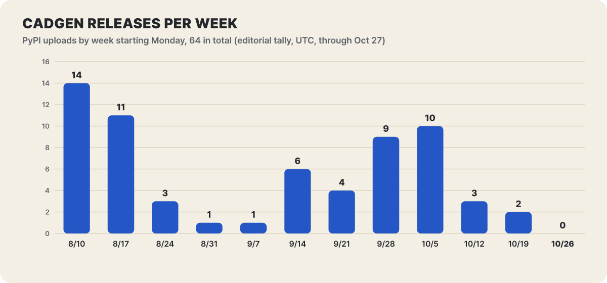 Figure 4. Releases per week (by PyPI upload date, tallied by our editors). There was a day with three releases, and the week of Oct 26 is 0 as of the 27th
Even though it varies from week to week, the flow is readable. 25 releases were packed into the first two weeks of August, it settled to one each in the first two weeks of September, and then nineteen poured out again in the weeks of Sep 28 and Oct 5. Between Oct 8 and Oct 20 alone came STEP checksum verification, the move of the API into a separate project that reads PyPI (0.7.19), the viewer redesign (0.7.22) and the five-language viewer (0.7.24), and the fix for the bug where mesh export failed when Node was not on the path (0.7.26). That last fix is directly tied to the STL export step in this article, so if cadgen stl build behaves oddly after installation, it is quicker to check the version first.
There are three places where the version gets pinned. Every command of the CAD skill runs with the release pinned, as in cadgen==0.7.26. The same number is also in the args of the Claude Desktop config, so you have to change it yourself when updating. When you update the plugin, the new release of cadgen is downloaded the first time it runs, and the previous release stays in the uv cache and can be cleaned up with uv cache prune. For copies you installed yourself, a blue update button appears at the top of CAD and on the home screen when a new release comes out, and pressing it puts an update request sentence into the conversation so the agent runs the per-app update command.
- Did you run
uvx cadgen telemetry offright after installing, before the first job? - Did you install only one of the plugin and the skills in each app?
- Did you add the
latestbranch to the end of the install command (mainincludes unreleased changes)? - Did you restart the app after updating, and for Claude Desktop, change the
cadgen==number inargsto the new release? - If you installed only the skills, did you run
addagain to update instead ofnpx skills update?